Tuesday, 12 August 2014

PARP PARP

My Build Buddy, Pete, sent me a parcel containing MVSA compliant wing mirrors, a cowl for my little spotlight and most importantly a serious hole cutter for cutting the 52mm holes in my dashboard for the instruments.

Now that's the job I really want to get stuck into, but I feel the need to get all the little jobs out of the way first. Firstly I enlarged the hole in the small bulkhead panel that fouled the riv-nut that secured the silencer back to the side.


Whilst the top GRP barrel decking was off, I decided to apply the self adhesive, 3mm foam strip to the underside of all the bolted down panels that surround the back wheels. These panels have to be removable so that the back wheel can be accessed, but they also need to be sealed to stop water getting intro the storage areas either side of the wheel. I ran out of the foam strip as I was the placing first length on the underside of the lid to the electric box, this application is not to stop water egress, but to prevent it rattling. The other photo shows all of the rear panels stripped of plastic and bolted in place.


Now it was time to fit the wing mirrors, these rather ugly black jobs will be replaced with neater chrome ones once MVSA has been granted and of course my smashing little swiveling spot lamp, complete with cowl will have to be removed for MSVA.


I couldn't resist the 'Parp Parp' bulb horn, a snip at £14 on Ebay, again will have to come off for MSVA, but good fun. Still got a few more jobs to get sorted, before I get started on the dashboard.

Thursday, 7 August 2014

A FISHY TAIL

For some while I had been scouring the internet for Brooklands style silencers with fish tail ends, I have found ideal, after market ones for Velocette motorcycles, but they are designed just to be fitted on one side of a bike. I found an ugly cast aluminium one, but eventually found these  stainless steel beauties from a kit "sports car" manufacturer who were happy to supply me. They came complete with reducers to fit my inch and a half pipes.


My piece of ali tubing came in handy again as I used a length to space the distance between the rear clamp and the side of the car. I used a length of M6 stud, a dome headed nut and a M6 riv-nut again backed by a drilled out penny washer. The result is that, in one go, the fishtail is clamped into the silencers and the whole lot rigidly fastened back to the car. Of course the drilled hole in the side of the car exactly matched where a small bulkhead is to be riveted, which necessitate a slot being cut into each of these bulkheads to accommodate the riv-nut, typical, never quite as straight forward as you think.


I need to polish up the spacer tube to look like stainless and I also feel that I would like to drill the customary holes on the outside of each fishtail, but I will mark the hole pattern onto paper first, stick it onto the fishtail and check out the appearance, before making a decision.

By the way, my little camera turned up, neatly stowed in the glove box.

Two other things, Arthur advised me that the bonnet is not as thin as I thought, it is 1.5mm thick and My Build Buddy Pete has pointed out sadly, that my beautiful bonnet catches are not MSVA compliant and I will have to change them to ones without the curled over finger hook. Ho Hum, lets hope the correct ones share the same fixing hole spacing.

Sunday, 3 August 2014

WHAT'S THE CATCH

Tick two off and add another five to the job list, never a dull moment, that is the plan. I initially allocated two to three years for the build and I am only a couple of months into the second year and I seem to be accelerating towards the finish line.

Apart from headlights and indicators, oh and of course, wheels and fenders, the front end looks almost finished, especially now now that I've removed the plastic film from the bonnet halves and fitted the securing catches. I drilled out the holes in both parts of the catches to take M4 button head bolts and used riv-nuts in the body and bonnet to attach the catches. I was concerned that the bonnet might deform as the aluminium is only 1mm, but I found that M6 washers placed over the back of the riv-nuts, before I pulled them, made for a solid fitting.


I really fancied an oil catch tank, shown in the CBS catalogue, complete with an air filter on top. I measured carefully and yes, it would fit onto the front of the drivers side foot well bulkhead, so I ordered it. When it arrived, it was every bit as beautiful as I had hoped, but was larger than I imagined, it did fit onto the bulkhead as planned, only, the filter part was mm's away from the steering column and I thought it unlikely that the MSVA testers would like that. Instead I mounted it onto the vertical chassis rail, which gave 25mm of clearance to the steering column. I spaced out the inner fitting with a bit of ali tubing, the width of the chassis rail and again I used a penny washer on the back of that riv-nut to stiffen the fitting.


All breather pipes connected and it does look the bizz, a little over the top maybe, considering it will hardly be seen once the side panel is reattached, but I like it!

Arthur pointed out to me that I said BMW Mini when I referred to the column mounted indicator switch, I meant, of course BMC Mini.

Also sharp eyed and keen readers, might wonder how I managed to post the above two photos on the 3rd of August, when they clearly show the date as the 4th. That won't happen again, as I've reset the date and time on the camera, but the strange thing is, that the little camera that I usually take into the garage, has totally disappeared, not surprising as I spend more time looking for the right tool or part, than I do in actually fitting it, age I guess! and I am sure it will turn up in the most unlikely place.

Monday, 28 July 2014

BACK IN THE BOX

With the excitement of fitting my new steering wheel over, it was back to the electric box to finish making the connections. I started with the single cable from the oil pressure switch, I first slipped protective sheath over the full length of the wire and then a piece of heat shrink before I soldered the two wires together, the heat shrink was then slid over the joint and shrunk with a hot air gun.


The same treatment was given to the two cables from the brake warning light switch and finally to the three wires from the voltage regulator. I used plastic, split, corrugated sleeving to protect this run, in the photo you can see the three wires protuding through the sleeving, after I slid the short lengths of heat shrink over the joins and shrunk them, I tucked the cables back into the corrugated sleeve and job done. I have to admit it doesn't look quite as orderly as I would have liked, but I am happy that all the connections are secure and any way, it will only be me peering into the box and scratching my head when the engine won't start.


The last photo shows the finished box. just got to screw the lid down. My little gas soldering iron, on left of photo has proved itself more than man enough for this job and it's great not to have a trailing cable getting in the way, also it means I don't have to run my generator, until I need to use the hot air gun.

Saturday, 26 July 2014

ONE WHEEL ON MY WAGON

I abandoned the electric box when UPS arrived with a package. I had had an email to advise me that a delivery from Moto Lita was on its way, bang on time at just over four weeks from confirming the order.

My first fear was, had my B&G quick release boss been included in the package and of course it had. The four spoke wheel was superb and the screw holes matched those in the top half of the quick release boss, the finishing touch was the 'Morgan' engraved central boss that would cover the screw  heads.


Something was wrong though, the hole in the boss wasn't splined and just wobbled about on the end of the steering column, a call to B&G racing told me that 'I needed a hub fitting kit' silly me!, but I was stumped when I was asked what car it was for, I told him I would call back. An email to Arthur was partway helpful, the column came from Westfield cars and was old British standard, to dot the i's, I measured the diameter of the spline, 18.5mm and counted the number of splines, approx 46. The next day I called B&G and with the above info they identified the kit and it arrived the next day, problem solved.

One slight problem remained, the Hub had a protruding ring which was intended for a steering wheel to sit over, but the base plate of the Q/R boss needed to sit flush, I carefully hack sawed off the ring and filed the top smooth, the above photo shows the sawn off ring and the abraded top of the boss, but this will be covered by the plate, so not a problem. The wheel is removed by pulling upwards on small paddles that protrude either side of the boss and simultaneously pushing in a small button, this is a two handed job and definitely cannot be accidentally done whilst driving. the boss is very securely located by a series of large ball bearings which eliminate any sloppiness or backlash.


It all fitted together very easily, although  I haven't actually bolted the hub onto the steering column yet, as it will have to come off to allow the dashboard to be removed. The photo immediately above shows what is left when the wheel is detached and you might well be asking, why I feel the need to remove the steering wheel at all, the reason is that it would be a tight squeeze sliding my long legs under the dash with the wheel in place. Even Morgan now fit detachable steering wheels to their production cars. I am pleased that I decided not to cut any holes in the dash until the wheel was in place, because it is evident, without yet sitting in the car, that some instruments/switches are obstructed by the spokes, so a little adjustment is required before I start cutting and drilling

Thursday, 24 July 2014

SPARKS FLYING

The next job on my list was the first of the dreaded ones, 'Sort out the electric box'!!

I started by removing the box and enlarging the two main holes at front and rear, but of course, to get the box out I had to first remove the exhaust pipe and the side panel. I had previously cut the new hole to the rear, but realised that it was a tight squeeze getting the four large bundles of cables through to underside of the dash, especially as I had yet to line the hole with rubber U channel, hence the need to get the electric file out.

That done I fitted riv-nuts to the back and bottom of the box and attached the block of relays and fuses to the back and the engine management box to the bottom. I then realised that before I put the box back into the car, I must first glue and rivet the left foot well bulkhead in place, so what was going to be a ten minute job, turned into a couple of hours. The plus side was that with the very warm weather the adhesive, sealant came out of the cartridge much more willingly, with the result that more overspill had to be cleaned up with copious quantities of white spirit.

The long bundle of cables that would eventually connect up to the rear lights and indicators at the rear of the car, also carried the cables that originally connected to the foot brake warning light switch. Obviously these cables needed to be rerouted to the pedal box under the bonnet,so the plastic sheath had to be split along its length and the required cables seperated out. I needed to splice one of them and my little gas soldering iron and heat shrink sleeving did a secure and neat job. The remaining exposed bundle of cables I rebound with self-amalgamating tape, which when stretched as you pull it tight around the cables, releases a resin and makes a watertight seal. This rebound part of the loom was also passed through the rear opening, beginning its journey to the back of the car


The box was starting to look tidy, but I still had to make the connection with the pedal box and all the other engine connection, although one or two cables were exactly the right length, for instance the wires to the starter and starter solenoid were perfect, just requiring a couple of cable ties to secure, but at least I have made a start and was very pleased with my first soldered connection

Tuesday, 15 July 2014

SO DASHING

Three small tubular spacers were cut from a length of ali. tubing, these were so that I could bolt the bottom of the dash board to a chassis cross member, I thought I would need to cut five, but the two outer pre-drilled holes in the dash didn't line up with the cross member, so I bent up a couple of brackets, drilled and inserted an M5 riv-nut into each one.


I marked the chassis rail and then removed the dash so that I could drill and insert the 5 riv-nuts, I bolted the two end brackets to the rail and offered up the dash and fortunately the riv-nuts and holes in the dash lined up.Three 60mm button head bolts went through the dash and tubing and into the nuts although I had to run a a tap through a couple of them to free up the thread. A couple of short bolts went through the two end holes and connected with the nuts that I had inserted into the brackets and all was rigid.


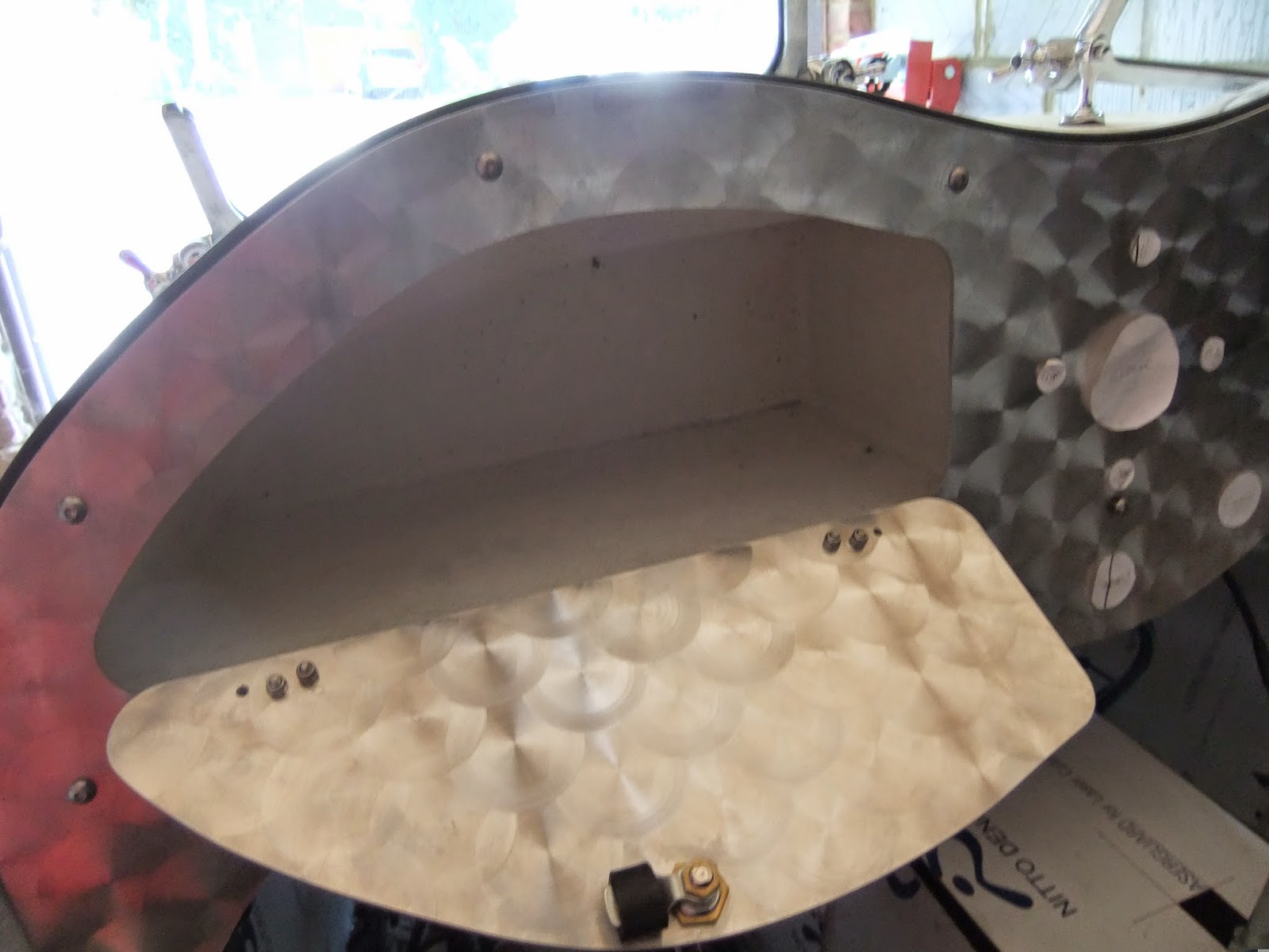
Whilst the dash was off the car I offered up the glove box lid and drilled and fitted the hinges, I ran out of M4 nuts and bolts, but had enough to ensure that it will stay put until I get some more. Arthur had provided me with a GRP moulded glove box, this was squeezed into place under the scuttle. I had been giving some thought as to how to fix this into position, but with the dash in place, it is so snug it can't possible move.


Arthur had told me to buy a column mounted indicator, dip,flash, horn switch for an old BMW Mini, he also provided a replacement backing plate and advised me to carefully remove the larger plate as fitted and the blue self cancelling plastic moulding, fit the new plate and open out the large hole sufficient so that it would go over the steering column and this I did. Unfortunately the pre-drilled hole in the dash was a bit snug. I had previously marked out were it fouled and whilst the dashboard was on the WorkMate I filed out the hole with my, very useful electric file, neat and quick and with the dash back in place I was able to wriggle the switch into position and tighten the clamping screw from behind the dash, mind you I have still got to work out with of the many wires does what.


A couple more weeks to wait for my steering wheel and removable boss, much longer than I had hoped. When Moto-Lita confirmed my order, whilst I was still in France, they quoted four to six weeks and four of those weeks are just about up, so not much longer and then the dash will  have to be removed to drill all those holes.