Monday 29 December 2014

READY FOR LIFT OFF

Just before Christmas I manage to sneak into the garage and get the cable for the rear pork pie lights P clipped down to the rear of the chassis and out the back, ready to connect to the lights. I also mounted the lights onto the highly polished, aluminium, rear light/numberplate board, but as yet I haven't got around to connecting them up, still that won't take long. However although the front of the board is mirror polished, the back isn't and as much of it is visible, I will have to take it off, at some point and polish the back side.


What had been occupying my mind, was the best way to lift Marjorie of the trestles. I had worked out that with a bit of help I could get my engine crane down the side of the garage so that with a couple of straps I should be able to lift her up, remove the trestles and gently lower her onto her wheels.

In readiness I bought a couple of ratchet adjustable straps from Machine Mart, they are actually for tying down a motorbike onto a trailer, but I was advised that they would be good for the job, each strap rated for 500kg and the car weighing in at less than 450kg they would be fine. On Saturday my mate Colin came round and he was easily persuaded to give me a hand in manoeuvring the crane into place and we discussed various options for dropping Marjorie in stages. The next day I messed about with the crane and repositioned the trestles as far to each end of the car as possible, allowing maximum adjustment of the cranes position to ensure that I got the balance position about right.


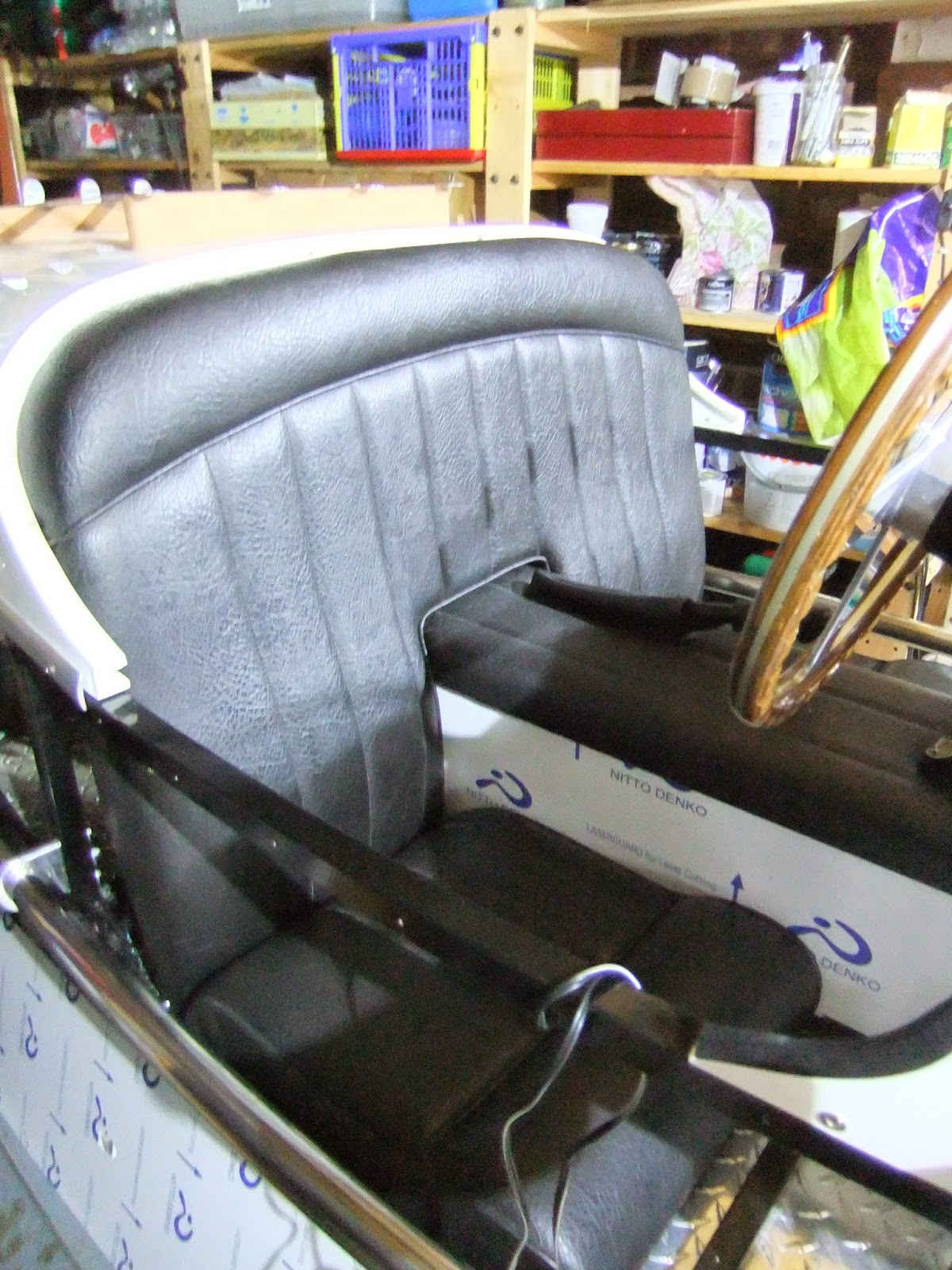
I placed clamps onto the bottom rail to stop the straps from slipping closer together, but when the straps met overhead and clipped onto the cranes hook, the front strap passed over the scuttle. I removed the little Brookland Screens and the steering wheel, but I was concerned that damage to the scuttle would occur as the weight of the car was taken.


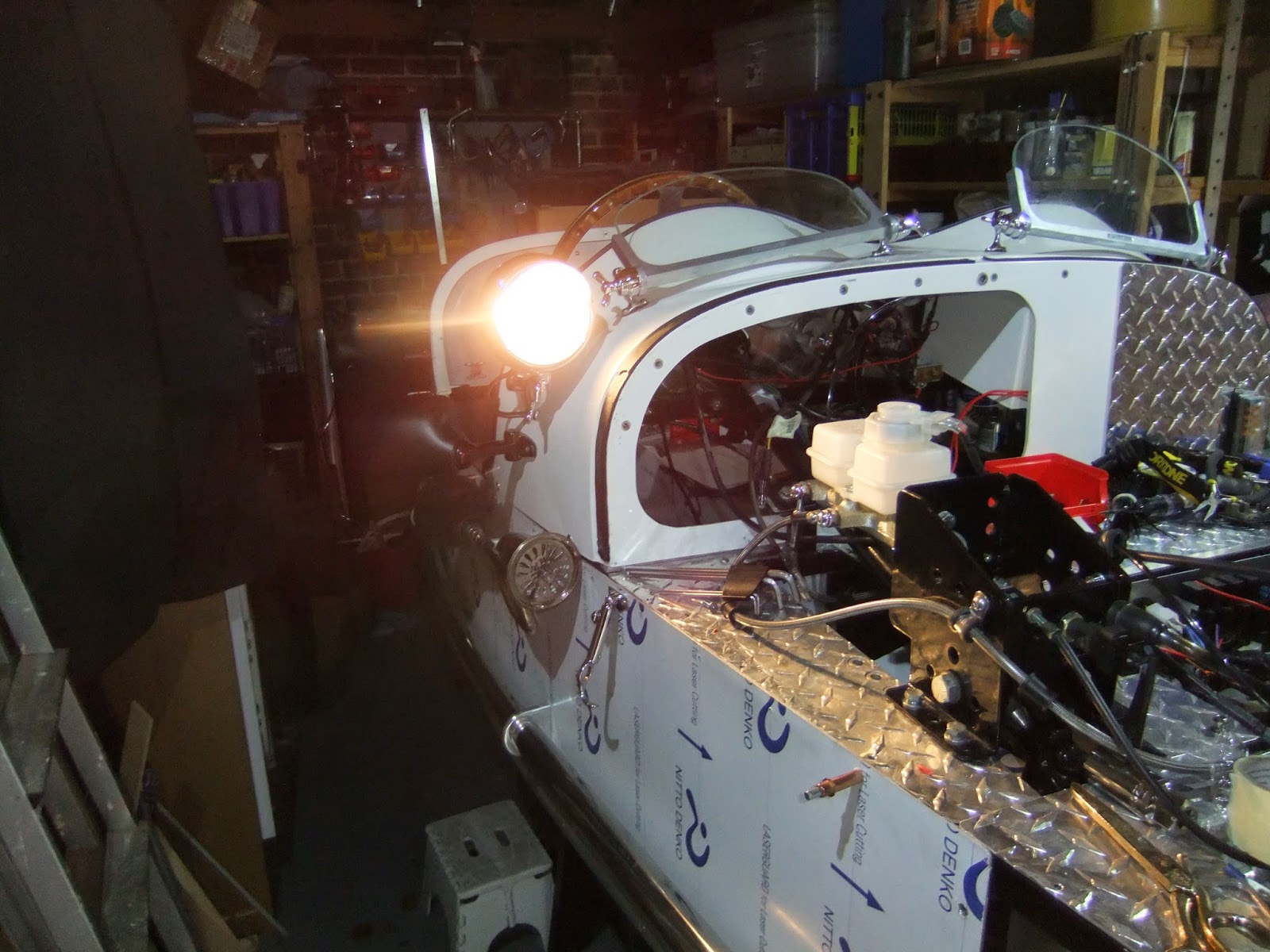
Another trip to Machine Mart produced a Load Leveller, which is intended for lifting engine/gearboxes in and out of a car, again it was good for 500kg and as the above pictures show it's good for the job. At 730mm in length it straddles the scuttle and fuel tank and with a small adjustment to the length of the front strap the car now lifts cleanly off the trestles. I am sure that the load leveller will come in handy for further engine removals on future projects, as I am afraid to say that the car building/restoration bug has bitten hard. The revised plan is now for a one stage lower to the ground, but with the front wheels onto ramps, which will make it easier to extract the crane legs from under the car. A quick final lift at the front to remove the ramps and we're there, ready to start the engine and drive out of the garage, to the flashing of cameras, popping of champagne, a roll of drums and much applause, must stop dreaming.

Monday 15 December 2014

GAITERS AND PORK PIES

Firstly I would like to thanks Peter, Carol, Dejavw and Sean for their congrats on my first engine start up, as moments go, they don't get much better, well, related to building a kit car that is.

Call me selfish or self indulgent, but I did find the time to finish connecting up the handbrake. I needed to order a nipple from CBS and whilst I was doing that I thought I might as well add onto the order, leather gaiters for the gear leaver and the handbrake. And whilst I was doing that I also ordered a pair of rear lights from Stafford Vehicle Components.

I didn't have the confidence in my soldering abilities to actually solder on a nipple to the handbrake cable, so I compromised and used a screw clamp nipple. Having tightened down the screw onto the cable as tightly as possible, I splayed out the wire as it exited the nipple and using plenty of flux and good old fashioned non fluxed solder, I applied it using just the flame from my mini gas soldering iron. The solder ran down between the the wire strands back into the nipple. For good measure I applied more solder into the hole opposite where the screw fits. I trimmed back the excess strands, and I now have a belt and braces job and am confident that the nipple will hold fast.


I finished of the job by P clipping the outer cable back to the chassis, ensuring that it would not foul the caliper or the swing arm as the suspension moves up and down.


The leather gaiters fit very nicely, they both need 3mm countersunk bolts to attach them, but I have yet to decide whether I use riv-nuts or regular nuts on the underside. Although more of a faff initially I think riv-nuts will make them easier to fit as now there is as not much movement to the handbrake lever to slide the whole top cap complete with gaiters into place.I do beleive that a nice wooden gear knob will be in my Christmas stocking on the 25th.


The rear lights are a reproduction of a Lucas pattern and were always referred to as Pork Pies, obviously their shape might have something to do with that. They will fullfill all my need as they incorporate indicators and number plate illuminations. I have already connected a length of cable to the loom with a six way connector block and now just have to route the cable to the back of the car in readiness to connect to the lights when fitted.

Thursday 4 December 2014

CONTACT, IGNITION

I was going to title this post, BLEEDING BRAKES, but events have overtaken the blog.

Well the brakes have been bled and the pedal travel is minimal, great! My new, one man brake bleeding tool arrived as well as the 12mm banjo for the back brake. The tool was only partially useful. but this was because almost every joint leaked, so initially I was sucking air rather than brake fluid down the pipes. I then pumped the brake pedal to push the fluid down the pipes and when I started to get a bit of pressure fluid started to spurt out of the T junction to both front brakes, I had to disconnect and move a few pipes and cables so that I could get a 10mm spanner to the T and tighten all three connectors, then it started to leak from from the left calliper, another half turn there and all was tight and leak free.

The back brake was easier with just the one calliper and Alan of Triking had previously advised that I remove the calliper from the wheel and turn it so that the bleed nipple was at the top. Good advise, the air bled out easily and apart from mopping up the spillage the job was done.


I connected the cable to the handbrake leaver, but there is too much slack in the cable, so I will have to cut off the nipple at the calliper end and solder on a barrel one at the correct distance. I also need to buy some P clips so that I can fix the brake cable firmly in place.

Having got as far with the brakes as I could, I removed the bonnet and engine cowling, which allowed me access to the right side carburetter. I think the leak from the carb was because the bottom of the float chamber wasn't fully tightened, certainly I couldn't blow air passed the float needle when I lifted the floats. I put it all back together, refitted the carb to the engine, turned on the ignition and the pump started to make its whirring noise and no petrol leaked out.

I couldn't resist it, although the car is still on trestles, with a fire extinguisher in hand, I pulled out the choke, and pressed the starter button, there was a pop from the left carb and a cough. I pressed the starter button again and with a little pump of the accelerator pedal the engine sprung to life and settled down into a steady tick over, fortunately it seemed quite stable on the trestles.

It was noisy at the back end, in fact one of the fish tails dropped out of the silencer as I hadn't tightened it properly and it will definitely need some stuffing in the silencer boxes. The garage quickly filled with exhaust gas, so I switched of the ignition and waited for the garage to clear. I started it again, first prod of the starter button this time and a quick check of the warning lights and instruments showed me that all was as it should be. The only warning light still glowing was the green neutral one.

Yippee!!!What a result, almost a bit of an anti climax really, as it was so quick and easy, but that made a good change. I have decided to leave Marjorie on the trestles whilst I finish off connecting the hand brake and wiring up the rear lights, but I have still got to ordering them yet and with Christmas fast approaching I don't expect to get much more done until the New Year.

Aplogises for not having taken any photos of the first start up, not sure how that would have worked anyway, but I am sure there will be plenty on launch day, in the meantime I can relax in the knowledge that Marjorie has the power to go and the ability to stop.

Friday 28 November 2014

ARE WE SITTING COMFORTABLE

The bundle of cables that will eventually supply the rear lights and indicators had been lying around on the floor of the car along with assorted nuts, bolts and tools and it was now time to tidy it all up. The cable was P clipped up inside the transmission tunnel along with the brake hose, the nuts, bolts and tools were put away and the floor vacuumed. The aluminium panels to the tunnel were temporarily bolted/riveted in place and now that all was neat and tidy I fitted the padded cover to the tunnel, followed by the seat back and the squads.


I must be honest, the real reason for doing this in that we have friends over this weekend and I want to show Marjorie off at her best. In fact though, once the hand brake is connected, the brakes bled and the right side carburettor sorted, she will be ready to come off the trestles and then I will most definitely want to climb aboard. In the meantime I have left both side panels off so that any adjustment will be easier to make.

Thursday 27 November 2014

BACK BRAKING

Both front wheels are now fitted, although there was a slight hiccough with the left wheel. The rubber bellows on the top ball joint had split open and when I removed it to replace it, I noticed that the taper of the threaded shaft of the ball joint was a loose fit in the tapered top hat. A trip to Arthur's confirmed that I had a faulty top hat and he immediately replaced it with one of the correct size. fortunately the split rubber highlighted this problem, before the wheels hit the ground.


I had previously fitted the back wheel complete with the original Brembo calliper and back plate, but this didn't allow for a hand braking. A call to Alan at Triking, who had supplied my Brookland silencers, was able to resolve this problem with a hydro/mechanical calliper and a special back plate. I posted, last Friday, the rear brake disc to Triking to allow Alan to get the proper alignment of plate and spacer tube and on Monday I had an email to say it was ready and on Thursday it arrived  complete with pads and handbrake cable. Wow that's seriously efficient.


I did a trial fit to the back wheel and it was perfect, with just enough clearance where it was needed. Alan had sent the back plate unpainted in case I had to make some minor adjustments, but as all was fine, I removed it and gave the plate several coats of smooth black Hammerite. 


Its all back in place now and I am awaiting a 12mm banjo so that I can connect the brake hose to the calliper and get those brakes bled.

Wednesday 12 November 2014

WHEELIE SURPRISED

I had arranged for a trip down to Ditchling last Friday, to collect seat back and squabs from Arthur. I was intending to fit a pair of bucket seats, but my wife insisted bucket seats just didn't have the traditional look and to ensure I keep on her right side I opted for form over function, still nothing that can't be changed at a later date and Arthur was offering a good deal. However to my surprise a text from Steve at Wheelwise told me my three wheels were ready for collection. So with my chum Gerry, it was two birds with one stone.

Arthur had the seat, plus tunnel capping and side panel cards ready and once loaded its was off to Cowfold, thirty minutes away for the wheels. Splendid, very shiny, already shod and ready to go.

I stashed my new goodies away and got on with a few outstanding jobs, like re-fitting the fuel tank and fuel pump. That done I wired up the fuel gauge and pump and after adding eleven litres of petrol the fuel gauge registered just under half full, so I expect the tank will hold about twenty five litres when full and the voltmeter showed 12 volts.


Before I connected the fuel lines to the carbs I turned on the ignition and with a whirring from the pump, fuel gushed out the end of the hoses, I deliberately did this to flush out any debris. However once connected and ignition turned on fuel still poured out of the right hand carb, left one was fine, so I will have to it take off the right one and strip it, probably the needle valve or float sticking, shouldn't be too much trouble to fix and then I will hopefully be able to start the engine.


Just to round off the day, I loctighted the bolts that attach the brake disc to the hub, fitted the brake discs to the calliper, greased the tapered roller bearings, gently taped in the grease seal and mounted the wheel to the previously fitted stub axle and finally tightened the castellated nut until the wheel became stiff to turn. I backed off the nut just enough to allow the wheel to turn freely and inserted the split pin. I slipped the brake calliper over the disc and bolted it onto the mounting plate. The domed hub caps, mudguards and stays are still to come.

The third wheel will be the spare and I mounted it on the back, but I need to devise a way to keep it in place. But not long now before I can lift Marjorie off the trestles and roll her out of the garage.for a proper photo call.


Monday 10 November 2014

THE FINAL FUSE

Finally I have the electrics sorted, not totally, as I am waiting for a replacement column mounted switch to arrive, as to put it bluntly I buggered the original one, but at least I know exactly where each wire needs to go.

I eventually traced the short circuit down to the front right indicator light, I had stupidly connected the supply to the earth, no wonder fuses kept popping. Although I now had a working circuit on both left and right indicators, I couldn't get the switch to work, probably burnt it out, anyway whilst I was puzzling over it, I saw exactly where the connection for the flasher needed to go, so no need for a separate switch on the dash, just need the new column switch.

The last thing to tackle was the hazard warning switch. With the old bike switch still attached, I pushed the button and great, all the lights flashed, so I snipped off the wires and connected them to the new switch in accordance with the wiring diagram in the CBS cataloge and again great, all the lights flashed, until I turned off the ignition. Bugger, the hazard lights also need to flash with ignition turned off and there is a permanently life wire to the switch; back to the wiring diagram again. I eventually worked out that I needed to run a wire from the switch, that would become life when the switch was depressed, this would go to the supply side of the flasher unit and would power the flasher unit when the supply from the ignition ignition was turned off.


I routed a wire with temporary connections to the flasher unit and hazard switch end and it worked. Hooray. I made proper connections, tidied everything up, taping loose cables etc and did a final check that all lights and instruments worked and then I put the top back onto the electric box. Job done!!

Saturday 1 November 2014

TO INDICATE OR NOT TO INDICATE

I knew that the electrics would cause a lot of head scratching and I was right. It has been two steps forward and one backwards all the way.

In the last post I said it was time for the column mounted switch to be sorted, so I started to sort it. I snipped of all the wires to the old left handlebar switch, having properly tagged them first. The new switch unit I removed from the steering column and laid out in front of the scuttle giving me plenty of room and light in which to work.and started with the dip/main beam connectors, all went well until I realised that in the main beam position both the main and dip were coming on together. I looked carefully at the switch and saw that one of the contacts had got bent, so no matter at what position the switch was in the dip beam was permanently on, a little deft tweaking of the contact with the pliers resolved this problem.


I then started to look where I could connect up the wires for the headlamp flashers, but to no avail, I don't think this function was intended with this switch, but that's easily solved by running the wires to a separate spring loaded switch to be fitted on the dash, behind the steering wheel.

Next were the indicators and again a problem, one of the main 15 amp fuses keeps blowing, I've had the switch apart and I don't think it's there, but when I ran out of fuses  I decided to call it a day and work on something else.


The hooters I took of the old bike and mounted them on the front end under the headlights and I think they look good, I saw that Henry Wright had already done that and if good enough for him, certainly good enough for me. Henry has just got his MG3 through the most stringent of test in Oz, well done Henry. This time all works well with a loud toot with just a push on the end of the indicator stalk.

I then set about the rest of the new instruments. I ran five wires back from my new fuse box, two are permanently live, provided the isolating switch is down, these are for the 12v socket and the clock. The other three wires are for the fuel pump, fuel gauge and the voltmeter, these are only live when the ignition switch is fully on.


I wrapped the cables in the split corrugated sheaf and clipped them up under the glove box. The 12v socket I mounted under the dash just to the right of the transmission tunnel, but out of the way of my left knee when I am entering or exiting the car. Hooray all the gauges worked when I powered up, so now nothing for it but to sort out the indicators as that is the only thing between replacing the fuel pump and tank and firing up the engine for the first time, now that will be a hooray occasion.

Monday 20 October 2014

I ONLY HAVE EYES FOR YOU

CBS provided me with a pair of budget headlamps and I got two pairs of short stem, bullet indicators from an Ebay supplier. I also got several metres of ten core 21 amp cable with which I would connect it all up.

I mounted the headlamps and decided where to drill through the shells to mount the indicators, they needed to be as far forward as possible otherwise the curve of the shell would have them pointing at the sky. That done I peeled back the tough outer sheaf of the cable, selected what colour cables I would use, seven of them and cut off the remaining three. I soldered together the wires for the headlamp and indicators and crimped on connectors for the side lamps.


Above photos shows right shell fully connected with lamp dangling and work in progress with the left. I fitted lamps and the peaks, but I didn't like the way the mesh covers fitted, they protruded too far out and for the moment I will dispense with them, maybe I will try to shorten the clips, but more important things to do first.


I ran the cables in split corrugated, sheaf, back to the electric box, cable tying securely as I went. Once in the box I exposed the coloured cables and started to join them together with crimp on connectors. The only cables I won't connect together are the two green and the purples ones as they are for the indicators, green for the left and purple for the right


I am only temporarily connecting into the eight way block until I am certain that I have the main and dipped wires the right way round and I will only be sure of that when the column mounted indicator/dip switch is fitted, guess what? that is the next job.

Sunday 19 October 2014

LESSON LEARNED

I didn’t forget to earth the regulator, that was the first job and then I went on to the lighting switch.

The new light switch just had screw down terminals so I only had to trim back the insulation and insert the wires. I knew that there was going to be a problem with the supply to the sidelights which was separate from the main lights, but after trying several alternative ways of connecting it, I simply fed the side lights from the headlamp feed, via the switch. I can still run on just sidelights, but only with the ignition on, so I can’t use them as parking lights, but who does these days?

The supply to the starter button and the new instrument lights I connected to the sidelight position on the switch and the now redundant supply to the sidelights I diverted to power my little, side mounted spot light.

Next was to run a couple of supplies from the ignition switch to the auxiliary fuse box, first one was to power the voltmeter, fuel gauge and the fuel pump, but only when the ignition switch was fully turned on, just one wire would do and then piggy backed to the other two fuse inputs.


 The other supply came from the permanently live position of the ignition switch and was to supply the 12v power socket and the clock. Here I made a big mistake, having fitted an isolator switch; I failed to turn it to OFF whilst making the connection. The result was, when I checked the circuits I had no power anywhere. After I spent an age puzzling what I had done I separated the main connector block to find that the connection of the main supply wire had melted, obviously there must have been a short circuit and this was weakest link in the circuit, there being no fuse up to the ignition switch. The only way to resolve this problem was to cut the wires both side of the block and bypass it. It was a fiddle, but when done full power was restored.  Lesson learned, when working anywhere on the wiring, ensure the switch is OFF.


The photo immediately above shows the red wire that now bypasses the main connector block and the empty block is awaiting the bunch of cables that will go to the column mounted indicator, dip/main switch, almost the next job.

Thursday 9 October 2014

DOWN TO EARTH

It has been a time of highs and lows. I completed the connections to the isolating switch. turned the switch to on, turned the key in the ignition and there they were, four bright lights shining on the dash board, oil pressure, generator, neutral and low brake fluid warning lights. I pressed the start button and the engine cranked over, yippee!!!! Just to be sure I pressed the button again and once more the engine cranked. I turned to get my camera to record this momentous occasion and all but the brake fluid light had gone out and no more cranking engine.

Bum!! I spent the next couple of days with my multi meter ensuring that there was power everywhere it should be. I tested the relays, the fuses, everything I could think off, but no joy. I studied an enlarged wiring diagram and noticed that the body of the regulator/rectifier was earthed, but I had mounted it on rubber riv-nuts, so it definitely wasn't earthed and then I thought that the engine was mounted to a thickly powder coated chassis, so maybe that was the problem, although I was getting a buzzing from my multi meter between engine and chassis, but thinking on, the brake fluid light was earthed to the chassis, but the other three warning lights are earthed onto the engine, so earthing the engine to the chassis seemed the obvious thing to do.


The original black cable that had connected the starter solenoid to the battery on the bike, was lying unloved and unused on the bench and it was exactly the right length to connect between a gearbox bolt and the new chassis earthing point for the Lucas battery. What do you know, all warning lights back on and engine cranking. I loved that bit of cable. The mystery though is why did the lights come on and the engine crank over in the first place, still happy enough that they do now and I can get on with the rest of the wiring, not forgetting to earth the regulator.

Saturday 4 October 2014

CONNECTED

After a week clubbing in Ibiza, work on Marjorie recommences. Well actually we weren't clubbing but celebrating my wife's son's wedding to his beautiful fiance and a great occasion it was.

The lights for the new gauges and the starter button have now been connected, I didn't take any photos as they would have been meaningless and anyway, somebody would tell me that I shouldn't have done it that way, but I do know I have got a good earth and as long as they all light up, I'll be happy.

The ignition switch and starter button have also been connected, but there is a slight complication with the light switch. The switch on the bike has two inputs, one from the headlamp relay, to switch on the headlamp and the other from the ignition switch for the sidelights, but the new switch for the car has only one position for input. To determine how I could resolve this issue I decided I needed to power up the system, so I ordered a Lucas 038 12v battery, Yea, I know Lucas don't exist any more, but the price was right. I also ordered terminal clamps and insulating covers. They all arrived yesterday, so I set to work.


I had to remove the left side silencer and front louvred panel to get the battery into position, but the whole side panel had to be removed to allow access to the isolating switch. I used my large step drill to cut a sizable hole in the foot well bulkhead, fitted a grommet and after soldering on a 6mm terminal on one end and a 10mm onto the other end of a length of 16mm2 red battery cable, I passed it through the grommet and connected the battery to the isolating switch. The original earth cable was just the right length and a 6mm riv-nut was fitted into the lower chassis rail to which the end of the cable was bolted to.


Battery was now wired up, including the link back to the starter motor. The above photo, looking up to the underside of the isolating switch shows the connections, not complete yet, as I still have to bring two wires through the grommet from the electric box, these wires come from the rectifier and the hazard light switch and need to be connected to the isolating switch, but I am one, 10mm ring terminal missing, Halfords here I come.


Tuesday 16 September 2014

SPAGHETTI JUNCTION

Nothing for, it was under the dash board I would go. I started with the really thick bundle of plastic sheathed cabling that would connect with terminals A & B, that emerged from the electric box, under the dash. I stripped off the sheath exposing all the cables and gently teased them out to their full length and it looked as if pretty much all the cables were long enough to reach their intended destination.


I started with the ignition switch, which had the same 1/4 spade connectors as the bike switch, so that would mean just swapping switches. I had though, spent along time with a magnifying glass and ruler tracing where each wire came from and with a multi meter on 'BUZZ' I worked out which cable connected to which terminal on the switch, that was relatively easy.


The lighting wire to the speedo and all the connectors for the tacho quickly connected, no problem.

Next was the eight warning lights, again I had worked out which coloured cable went to which light. This time I would have to change the connectors to 1/4 spade from the 3/16 ones on the end of each cable, a couple of times I forgot to slip the insulating sleeve on before crimping the connector, but fortunately there was just enough spare wire to do it again, with insulating sleeve in place. Six of the lights are grouped fairly close together and the wires reached the warning lights connectors without difficulty. I did have to extend the wires to the two indicator warning lights as they were placed either side of the steering wheel.


The only item left to connect from this bundle is the switch for the Hazard Warning Indicators, but I've left this for the time being and concentrated on tidying up the cables by stuffing them into the split, corrugated tubing, the above photo shows the first few inches inside the tube.


 At last all the cables were in and the tube was cable tied every few inches to prevent any escapes, a final cable tie secured it all to the cross chassis rail and connectors A & B were pushed together.  Lighting and start switches are next on the agenda, but at least I have begun to tame Spaghetti Junction.

Saturday 13 September 2014

NO MORE GUESSING

It was time for 'Fuel Gauge Sender' to be fitted. This bit of kit comprised a plastic float, some long length of stiff wire and a circular disc with the mystery boxy part attached underneath, I've no idea how it works and holes drilled around the rim, oh, I nearly forgot, a circular cork gasket.


The tank had to be removed so that I can access the rear of the dash board for when I start wiring up, ( next job, can't put it off any longer ) this made life easier, as the area where the sender was to fitted had to ground smooth as the propellor pattern would prevent a fuel tight seal. I decided where I was going to fit the sender, drew a circle around the gasket and set to with a, not to aggressive, flap wheel on the angle grinder and when I was happy that the surface within the circle was flat, I drew another circle around the inside of the gasket, dot punched and drilled just inside this circle. A hack saw blade in my jigsaw joined up the holes and small flap wheel in the electric drill, smoothed it out .

I marked the first fixing hole, drilled and fitted a countersunk 4mm riv-nut. I find it more accurate to firmly attache an item by one screw, before drilling the rest of the holes, this usually results in them all lining up accurately and this is what I now did.


There came with the sender a guide as to the distance between the float and mystery box, the length was dependent on the depth of the tank. The two stiff bits of wire were clipped together with three little clips and adjusted to give a length 165mm, I snipped of the excess. The wires were then soldered together, ensuring that the float was at the correct angle.


Gasket goo was applied to both sides of the cork gasket and the float was inserted into the hole and the top plate lined up with the holes in the gasket and top of the tank and gradually the six littlebolts  were evenly tightened down. Dash board here I come

Wednesday 10 September 2014

WHEELWISE

The second fishtail has been successfully drilled and it was time to order my wheels, in the knowledge that it would take about a couple of months for them to be made.

A trip to Wheelwise Engineering in Cowfold Sussex with a chum of mine, was arranged for Monday and aluminium rims, stainless spokes, hubs, tyres, inner-tubes and rim tape, all times three, were placed on order with Steve. Payment for parts was made leaving just the labour aspect to pay when the wheels are ready.


As we were leaving, I asked Steve if he could recommend a hostelry and he did. The Plough at Lower Beeding Nr. Horsham. He didn't mention though that it was a real bikers pub. The landlord had a beautiful Triton and a Bonneville standing outside in the car park, sparkling in the sunshine. Inside, in the fireplace, was a Vincent Comet, the single cylinder one, magnificent. On the other side of the room, sitting on a table was a Francis Barnet in totally original condition. The photos are not of the best as thay were taken on my phone.


The food was equally excellent and sitting outside in the warm sunlight, eating  great food and admiring the bikes finished off a successful outing and I seriously suggest you try out this pub if you are ever down that part of the world.

Sunday 31 August 2014

TWENTY EIGHT LITTLE HOLES

The dot punching was not a problem, but my initial attempts to drill the first of the 28 pilot holes into the fishtail was hard work. Being so used to drilling into aluminium I started off slowly, with my battery drill, but the bit didn't bite into the stainless steel, through the paper template no trouble, but then just a dimple.

I put a new 3.2mm bit into my electric drill, cranked up the generator and using more pressure and higher speed, the bit eventually started to cut and then I was on a role.


After the first few pilot holes were drilled, I tried opening them up with a regular 6mm bit, but that caught and stalled the drill, so I used a step drill. I put a 6mm washer over it and as the hole was cut and the drill punched through, the washer prevented the next 8mm step from starting to cut.


When the last hole was cut, I removed the remains of the paper template, cleaned off the sellotape residue with white spirit and gently ran a large countersink into each hole to clean them up. I finished of with a stiff polishing mop on the electric drill to remove the last little bits of swarf and the first one was done. I'm saving the other one for tomorrow as my shoulder is now aching.

Saturday 30 August 2014

BITS AND PIECES

I decided that before I got stuck into wiring the dashboard, I would finish off some of the outstanding little job.

First task to be crossed off the list was to connect the cable from the new choke knob into the sliding connector tube that links with the choke cables from the two carbs. All three cables are located in a circular block by small nipples on their ends and rather than try and solder a nipple on the end of the new cable, I tried various methods of connecting the new cable to the one from the connector tube.

It was soon obvious that this approach wasn't going to work so I experimented with making a solder nipple on a spare bit of cable. By letting gravity pull molten solder down the last few mm. of cable it formed a perfect blob, or nipple, right on the end of the cable. Happy that I could do this again, I cut the new inner and outer cable to length, threaded it through an adjuster and made a solder nipple as before. I reconnected all three cables into the connector tube, adjusted out the slack and it works.


Next job was to fit the MSVA required plastic sleeves to the track rods, these are to protect pedestrians from the edges of the adjustment and lock nuts in the event of an accident. It required the track rod ball joints to be separated from the steering arms, so that the sleeves could be slipped onto the rods, but as they hadn't been fully tightened this wasn't a problem.


The louvered front number plate carrier flexed at the right angle bend and I could imagine it flapping up and down at speed, so I bent up a couple of 2mm strips and riveted them onto the underside, that should resolve a potential problem.


Final job of the day was to determine the configuration of holes that I wanted to drill in each of the silencers fishtails. I drew up two patterns of seven holes a side, one at 1.5cm and the other at 1.25cm centres and drilled them into scrap timber.


I have decided to use the larger centre pattern and drew out another couple of paper patterns which are now stuck to the fishtails and await drilling.


Dot punch, hammer and 6mm drill bit at the ready and tomorrow I hope to get that job sorted and then it's fitting the fuel level sender to the top of the fuel tank.