Saturday, 1 February 2014

RACKED AGAIN

Racked, but this time it's steering. The front louvred plate bearing my RAC and AA badges had to be removed to expose the steering rack brackets and Arthur had conveniently provided a small piece of packing material to be placed under the near side of the rack to level it up and that was fine. When I went to pass the bolts through the rear holes in the clamping bracket, they fouled the front engine bolt. This was because I had temporarily used the old bike bolts, which at the front, is too long by about four inches and the overhang got in the way. Fortunately I had recently placed an order with Westfield Fasteners which included the correct engine bolts. Once again the engine crane was deployed to take the weight of the engine whilst I changed the front bolt, the first photo shows the nut attached to the new front bolt just allowing clearance for the nut of the clamp bracket. No problem now, the rack was firmly bolted down and level.


I quickly realised it was easier to join the two sections of the column together at the middle UV joint, before passing it down through the cockpit and loosely bolting the sheath to the chassis brackets. It took a bit wriggling to get the bottom UV joint onto the racks splined shaft, but eventually it slid in and the bolt was passed through the groove in the splines. I tightened the four bolts at the brackets, adjusting the column so that it passed centrally between the clutch and brake pedal, but one of the bolts securing the mid UV joint kept knocking against both pedals as the shaft was turned.


I took it all out and cut off the protruding excess threaded part of both bolts with my disc cutter, cleaned up the ends and passed the column back in again, but it still fouls the break pedal, not ideal. I will try adjusting the brackets to see if a slight angle solves the problem, if not I will move the pedal box back an inch or so as I had placed it as far forward as it can go, allowing for my long legs.

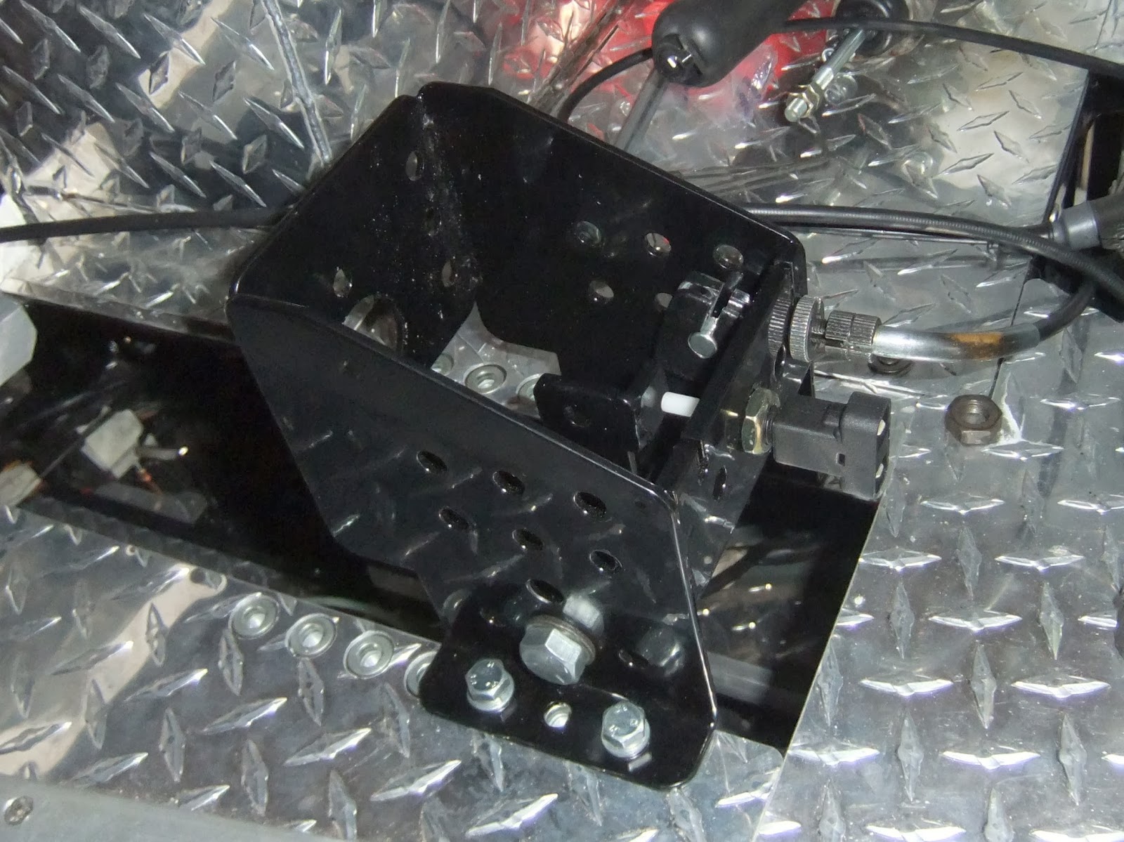
That was yesterday and today I took it all out again as the front foot well bulkhead had to be riveted in place first, so that the steering column could be passed through the hole in the bulkhead. Once that was done, when I reinstalled the pedal box I moved it back a tad and the break pedal is now in front of the UV joint nut and there is no interference. There is, as the photo shows a large flat flange on the pedal, I imagine that this is to increase stiffness of the pedal and I see no reason why I couldn't grind a little away to allow clearance should I need all available leg room, but it might also be, that when the break system is pressurised with hydraulic fluid, the pedal won't depress anywhere near as far back as the UV joint, we shall see.


Final photo shows the bulkhead glued and riveted in place, despite putting the tube of adhesive sealant on top of the hall radiator overnight, it still took a mighty effort to squeeze it out of the tube. It obviously cooled off very quickly, maybe whilst in the garage I should keep it in a bucket of very hot water, that might be the answer on these cold mornings.


Thursday, 30 January 2014

TREASURE

I am happy to report that things are back on track with Arthur and last Tuesday I and a chum had a trip down to Ditchling in Sussex to visit Arthur in his man cave, well actually much more like a cavern. I can only dream of having so much space and that many tools, even if I knew what to do with them.  Two left hand drive Beetle Backs were in production for customers in the USA, but most importantly there was a pile of goodies that had my name on them. TREASURE, steering rack, steering column, petrol tank, pedal box, master cylinders, handbrake lever and brake lines, now we can really get a move on.

Suspension shouldn't be much longer and an order was confirmed for exhaust pipes, dashboard, gear linkage, prop shafts, reversing gearbox etc. I had a list of queries which we talked through and I came away very excited and anxious to get the spanners out.


Despite the cold damp weather I wrapped up well and laid my new goodies out for the obligatory photo, the petrol tank although in its correct position has yet to be bolted down, but came complete with a lovely Monza style filler cap.

First job was to fit the pedals into the pedal box, the fit of each pedal on the shaft was too snug and the surplus black powder coat paint had to be filed away. It was the same problem between each pedal, but with some serious filing the pedals eventually swung freely back and forth after the box was bolted down. I intended to fit the bikes original clutch cable, but I had to drill out the hole at the top of the pedal for the nipple and also to widen the split to allow the nipple to rotate freely. I used the old hand break adjuster and although the cable is a tad too long I found a good route for it, that is out of sight with no tight bends and it works well. The photo show the mechanical break warning light fitted, but the rod from the master cylinder needs to be shortened and a clevis fitted before that can be bolted on.


Next job is to fit the steering rack and column, better get the steering wheel ordered.

Wednesday, 22 January 2014

RACKED

The little job of the luggage rack that I mentioned in the my last posting is now almost complete. The wood supports have to be removed and given a final sanding before varnishing. The aluminium straps are 30mm wide by 2mm deep, there is very slight flexing, but I thought that if I went up to 3mm I might have trouble bending the little upstand at the tail end, that I considered necessary to prevent luggage from slipping backwards under fierce acceleration. May be a quaint wicker basket would be appropriate? I think it looks the business and that the proportions are right. By the way, the little pot of paint was exactly the right size to give me the line to grind and sand the ends to.


The 6mm countersunk bolts go all the way through the wood and the GRP before being bolted up behind two 20mm wide ali strips, one fore and the other aft, that run from side to side so the stress on the GRP is spread evenly. When the rack is finally attached, probably after the car is sprayed, I will use a length of double sided tape between the the wood and the GRP to take up any gaping between the two

On a sadder note my relationship with Arthur of Aerocyclecar, the maker and supplier of my kit has come to an end. This will make the project a little more challenging as I will now have to independently source parts, but I have been promised help in that direction from somebody, who completed his car last year. With a bit of luck it may be quicker this way, although some parts may have to be special one offs, but one step at a time and the first is steering and suspension, I''ll let you know.

Saturday, 11 January 2014

CHRISTMAS BLING

Happy New Year to anyone reading this post and to celebrate it I have attached three of my wife's Christmas presents to the car.

First on was the Spread Eagle bonnet mascot, not quite the same, but very similar to Moto Guzzi's eagle motif that I applied to the alternator cover.Then the replica RAC and AA badges were pop riveted on, just to add a bit of nostalgia, those were the days, when a patrolman would snap a smart salute to a passing car bearing the appropriate badge


Next job is to make the luggage rack for the back of the car. I have a length of African hard wood, which my circular saw will cut down the middle to create the supports for the ali strips. The hard bit will be getting the underside of the wood to the same curvature of the GRP back panel, but I am sure I'll get there in the end.

Sunday, 22 December 2013

SCREENS 1 & 2

Not much inducement to get out into the cold damp garage at the moment, but there were a couple of jobs I wanted to get done before Christmas.

The rubber bobbins, I had got from EBay, for mounting the coil pack were in danger of getting lost, so I thought it wise to decide the best place for them and get the job done, only four holes to drill, didn't take long, just had to ensure the coils cleared the closed bonnet and that the HT leads had an unobstructed run to the plugs.


In lieu of anything else important to do I ordered a pair of Aero Screens, Brooklands style. £55 each, excellent, although the aluminium frames will need a bit more polishing, but as you probably know by now, I like polishing. I took my time in measuring and marking where the holes for the support brackets needed to be and then drilled them using a 4.5m drill for the 4ba bolts which would allow a little wriggling room for alignment. I made up four brass backing plates out of an old letter box internal flap, to spread the load on the underside of the scuttle. Job done, starting to look the biz.


Hopefully the New Year will bring forth steering and suspension parts from Arthur and allow me to move things on, in the meantime I will make a start on sorting out the wiring loom.

Merry Christmas and a Happy New Year to anybody out there who happens to have nothing better to do than read my little blog.

Friday, 6 December 2013

FINISHED WITH ENGINE

Tappets have been adjusted, 0.15 mm for exhaust and 0.10mm for inlet, the socket on the alternator nut allowed me to turn the engine over so that each piston was at TDC on the firing stroke, thus ensuring that the pushrods were at their lowest position before the feeler gauge was introduced between the tappet and the valve stem.

The remains of the, well and truly stuck on, gasket was removed from the underside of the rocker covers. New gaskets were in place  and the covers were bolted back on, after another quick polish.


Whilst I was unscrewing the second of the two screws on top of the left hand carb, in preparation to reconnecting the throttle cable, I failed to hold down the top and like a jack in the box, as the last thread of the screw released the top and spring sprung out. The spring I  found on the floor on the other side of the garage, but the top totally dissapeared. I assumed it must have gone even further than the spring, but despite fruitlessly turning the garage inside out I gave up looking for it and set about connecting the other carb, ensuring that I held the top down. All went well and as I adjusting the cable, there was the other top, not more than four inches away tucked down between the two cylinders, what a relief.

The throttle cable was soon connected to that carb and then the whole lot was liberally sprayed with the ACF-50 anti corrosion spray, just going to leave it now for the spray to creep into all the nooks and cranies before wiping off the excess. I have to say that I am very pleased with the finished appearance of the engine. Smug Git


One last thing, I have resolved my problem with getting a plug socket passed the chassis side rail and onto the spark plugs, a new 3/8 drive one just slips in and an adjustable wrench on the hex end of the socket allowed me to tighten the plugs.

Monday, 2 December 2013

TOPS ON

Last Wednesday I collected my bits from Dave at www.tsrvapourblasting.co.uk and I wasn't disappointed. Shiny bright, thanks Dave. He assures me that the carbs have been reset to pre. dissasembly setting since emerging from the ultra-sonic bath, but may need slight adjustment once engine is running.


The photos show the newly cleaned parts, plus the new carb filters, oil line to rockers and polished ali alternator cover. Time to put it all back together again. First on was the sump pan, not forgetting the new oil filter and then the laborious task of valve grinding, thankfully only four valves.
Valves were reinstalled using my trusty old valve spring compressor and plenty of oil down the valve guides.


I have plenty of piston ring compressors, ranging from small, which must have been for my first Villiers powered 2 stroke motor bike, up to a big bugger which was probably for my AJS 500cc single, anyway it has marked on it 2/6d so I have had it a long time. A slightly longer screw to hold it together and it slipped over these 530cc pistons a treat. The weight of the cylinder sliding down the studs was sufficient to push the compressor to the bottom of the piston where I unscrewed the clamping screw and gently pulled the compressor out around the studs. Off course I had to raise the engine to give clearance for the cylinders and heads to drop into place, but it all went very smoothly.


 Fortunately I had not forgotten the two O rings which go over the top and bottom studs before the cylinders are dropped on, and then the other 4 O rings are placed over the other studs before the rocker cradle is postioned over them and the whole lot is bolted down to 30psi, that was after the engine was lowered and secured in the chassis.


 I oiled the ends of the push rods and located them down their respective shafts before the rocker gear was installed, again using a liberal amount of oil over the securing pins. Just remains to adjust the tappets and refit the rocker covers.