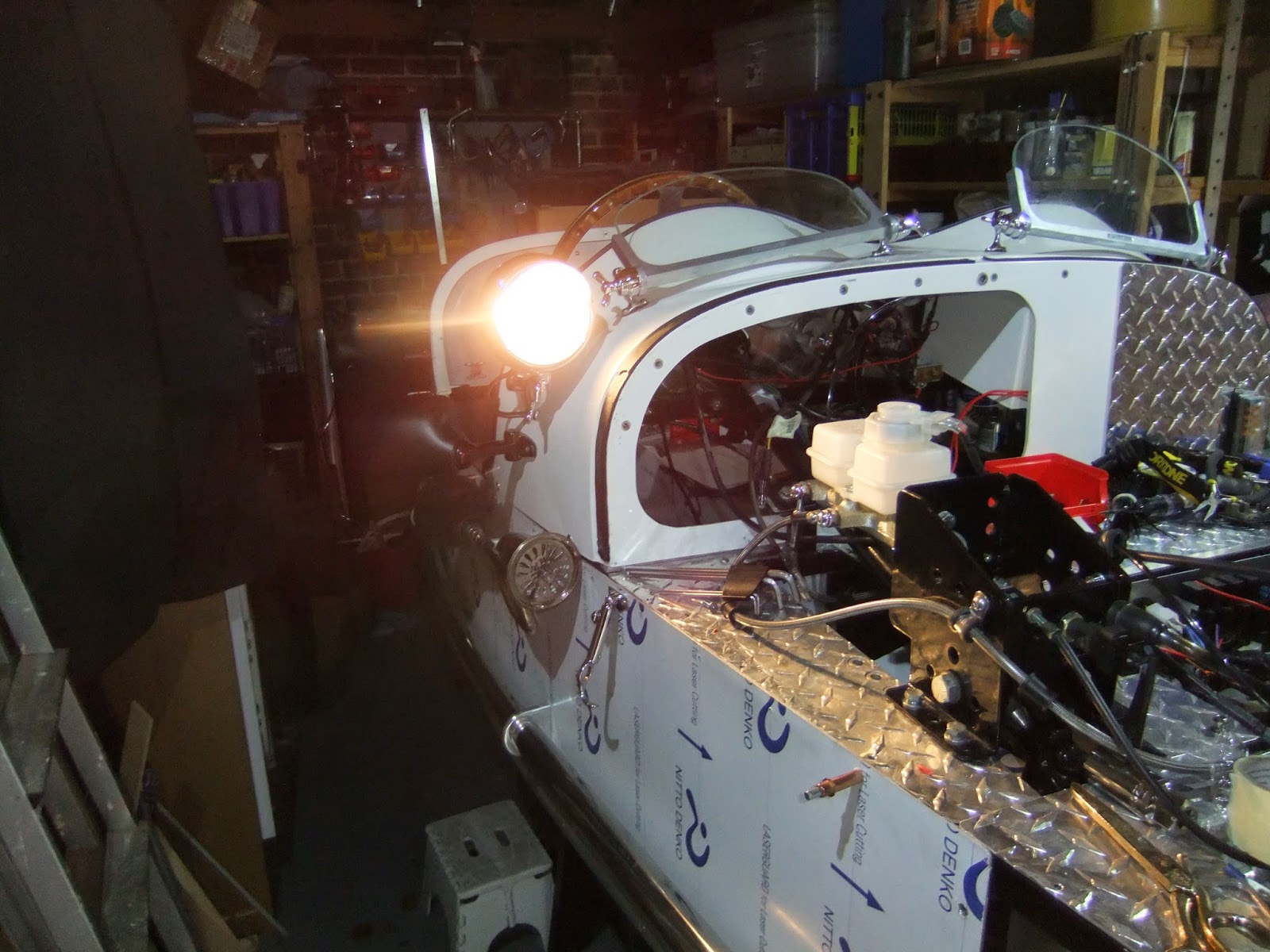
I had arranged for a trip down to Ditchling last Friday, to collect seat back and squabs from Arthur. I was intending to fit a pair of bucket seats, but my wife insisted bucket seats just didn't have the traditional look and to ensure I keep on her right side I opted for form over function, still nothing that can't be changed at a later date and Arthur was offering a good deal. However to my surprise a text from Steve at Wheelwise told me my three wheels were ready for collection. So with my chum Gerry, it was two birds with one stone.
Arthur had the seat, plus tunnel capping and side panel cards ready and once loaded its was off to Cowfold, thirty minutes away for the wheels. Splendid, very shiny, already shod and ready to go.
I stashed my new goodies away and got on with a few outstanding jobs, like re-fitting the fuel tank and fuel pump. That done I wired up the fuel gauge and pump and after adding eleven litres of petrol the fuel gauge registered just under half full, so I expect the tank will hold about twenty five litres when full and the voltmeter showed 12 volts.
Before I connected the fuel lines to the carbs I turned on the ignition and with a whirring from the pump, fuel gushed out the end of the hoses, I deliberately did this to flush out any debris. However once connected and ignition turned on fuel still poured out of the right hand carb, left one was fine, so I will have to it take off the right one and strip it, probably the needle valve or float sticking, shouldn't be too much trouble to fix and then I will hopefully be able to start the engine.
Just to round off the day, I loctighted the bolts that attach the brake disc to the hub, fitted the brake discs to the calliper, greased the tapered roller bearings, gently taped in the grease seal and mounted the wheel to the previously fitted stub axle and finally tightened the castellated nut until the wheel became stiff to turn. I backed off the nut just enough to allow the wheel to turn freely and inserted the split pin. I slipped the brake calliper over the disc and bolted it onto the mounting plate. The domed hub caps, mudguards and stays are still to come.
The third wheel will be the spare and I mounted it on the back, but I need to devise a way to keep it in place. But not long now before I can lift Marjorie off the trestles and roll her out of the garage.for a proper photo call.
Wednesday, 12 November 2014
Monday, 10 November 2014
THE FINAL FUSE
Finally I have the electrics sorted, not totally, as I am waiting for a replacement column mounted switch to arrive, as to put it bluntly I buggered the original one, but at least I know exactly where each wire needs to go.
I eventually traced the short circuit down to the front right indicator light, I had stupidly connected the supply to the earth, no wonder fuses kept popping. Although I now had a working circuit on both left and right indicators, I couldn't get the switch to work, probably burnt it out, anyway whilst I was puzzling over it, I saw exactly where the connection for the flasher needed to go, so no need for a separate switch on the dash, just need the new column switch.
The last thing to tackle was the hazard warning switch. With the old bike switch still attached, I pushed the button and great, all the lights flashed, so I snipped off the wires and connected them to the new switch in accordance with the wiring diagram in the CBS cataloge and again great, all the lights flashed, until I turned off the ignition. Bugger, the hazard lights also need to flash with ignition turned off and there is a permanently life wire to the switch; back to the wiring diagram again. I eventually worked out that I needed to run a wire from the switch, that would become life when the switch was depressed, this would go to the supply side of the flasher unit and would power the flasher unit when the supply from the ignition ignition was turned off.
I routed a wire with temporary connections to the flasher unit and hazard switch end and it worked. Hooray. I made proper connections, tidied everything up, taping loose cables etc and did a final check that all lights and instruments worked and then I put the top back onto the electric box. Job done!!
I eventually traced the short circuit down to the front right indicator light, I had stupidly connected the supply to the earth, no wonder fuses kept popping. Although I now had a working circuit on both left and right indicators, I couldn't get the switch to work, probably burnt it out, anyway whilst I was puzzling over it, I saw exactly where the connection for the flasher needed to go, so no need for a separate switch on the dash, just need the new column switch.
The last thing to tackle was the hazard warning switch. With the old bike switch still attached, I pushed the button and great, all the lights flashed, so I snipped off the wires and connected them to the new switch in accordance with the wiring diagram in the CBS cataloge and again great, all the lights flashed, until I turned off the ignition. Bugger, the hazard lights also need to flash with ignition turned off and there is a permanently life wire to the switch; back to the wiring diagram again. I eventually worked out that I needed to run a wire from the switch, that would become life when the switch was depressed, this would go to the supply side of the flasher unit and would power the flasher unit when the supply from the ignition ignition was turned off.
I routed a wire with temporary connections to the flasher unit and hazard switch end and it worked. Hooray. I made proper connections, tidied everything up, taping loose cables etc and did a final check that all lights and instruments worked and then I put the top back onto the electric box. Job done!!
Saturday, 1 November 2014
TO INDICATE OR NOT TO INDICATE
I knew that the electrics would cause a lot of head scratching and I was right. It has been two steps forward and one backwards all the way.
In the last post I said it was time for the column mounted switch to be sorted, so I started to sort it. I snipped of all the wires to the old left handlebar switch, having properly tagged them first. The new switch unit I removed from the steering column and laid out in front of the scuttle giving me plenty of room and light in which to work.and started with the dip/main beam connectors, all went well until I realised that in the main beam position both the main and dip were coming on together. I looked carefully at the switch and saw that one of the contacts had got bent, so no matter at what position the switch was in the dip beam was permanently on, a little deft tweaking of the contact with the pliers resolved this problem.
I then started to look where I could connect up the wires for the headlamp flashers, but to no avail, I don't think this function was intended with this switch, but that's easily solved by running the wires to a separate spring loaded switch to be fitted on the dash, behind the steering wheel.
Next were the indicators and again a problem, one of the main 15 amp fuses keeps blowing, I've had the switch apart and I don't think it's there, but when I ran out of fuses I decided to call it a day and work on something else.
The hooters I took of the old bike and mounted them on the front end under the headlights and I think they look good, I saw that Henry Wright had already done that and if good enough for him, certainly good enough for me. Henry has just got his MG3 through the most stringent of test in Oz, well done Henry. This time all works well with a loud toot with just a push on the end of the indicator stalk.
I then set about the rest of the new instruments. I ran five wires back from my new fuse box, two are permanently live, provided the isolating switch is down, these are for the 12v socket and the clock. The other three wires are for the fuel pump, fuel gauge and the voltmeter, these are only live when the ignition switch is fully on.
I wrapped the cables in the split corrugated sheaf and clipped them up under the glove box. The 12v socket I mounted under the dash just to the right of the transmission tunnel, but out of the way of my left knee when I am entering or exiting the car. Hooray all the gauges worked when I powered up, so now nothing for it but to sort out the indicators as that is the only thing between replacing the fuel pump and tank and firing up the engine for the first time, now that will be a hooray occasion.
In the last post I said it was time for the column mounted switch to be sorted, so I started to sort it. I snipped of all the wires to the old left handlebar switch, having properly tagged them first. The new switch unit I removed from the steering column and laid out in front of the scuttle giving me plenty of room and light in which to work.and started with the dip/main beam connectors, all went well until I realised that in the main beam position both the main and dip were coming on together. I looked carefully at the switch and saw that one of the contacts had got bent, so no matter at what position the switch was in the dip beam was permanently on, a little deft tweaking of the contact with the pliers resolved this problem.
I then started to look where I could connect up the wires for the headlamp flashers, but to no avail, I don't think this function was intended with this switch, but that's easily solved by running the wires to a separate spring loaded switch to be fitted on the dash, behind the steering wheel.
Next were the indicators and again a problem, one of the main 15 amp fuses keeps blowing, I've had the switch apart and I don't think it's there, but when I ran out of fuses I decided to call it a day and work on something else.
The hooters I took of the old bike and mounted them on the front end under the headlights and I think they look good, I saw that Henry Wright had already done that and if good enough for him, certainly good enough for me. Henry has just got his MG3 through the most stringent of test in Oz, well done Henry. This time all works well with a loud toot with just a push on the end of the indicator stalk.
I then set about the rest of the new instruments. I ran five wires back from my new fuse box, two are permanently live, provided the isolating switch is down, these are for the 12v socket and the clock. The other three wires are for the fuel pump, fuel gauge and the voltmeter, these are only live when the ignition switch is fully on.
I wrapped the cables in the split corrugated sheaf and clipped them up under the glove box. The 12v socket I mounted under the dash just to the right of the transmission tunnel, but out of the way of my left knee when I am entering or exiting the car. Hooray all the gauges worked when I powered up, so now nothing for it but to sort out the indicators as that is the only thing between replacing the fuel pump and tank and firing up the engine for the first time, now that will be a hooray occasion.
Monday, 20 October 2014
I ONLY HAVE EYES FOR YOU
CBS provided me with a pair of budget headlamps and I got two pairs of short stem, bullet indicators from an Ebay supplier. I also got several metres of ten core 21 amp cable with which I would connect it all up.
I mounted the headlamps and decided where to drill through the shells to mount the indicators, they needed to be as far forward as possible otherwise the curve of the shell would have them pointing at the sky. That done I peeled back the tough outer sheaf of the cable, selected what colour cables I would use, seven of them and cut off the remaining three. I soldered together the wires for the headlamp and indicators and crimped on connectors for the side lamps.
Above photos shows right shell fully connected with lamp dangling and work in progress with the left. I fitted lamps and the peaks, but I didn't like the way the mesh covers fitted, they protruded too far out and for the moment I will dispense with them, maybe I will try to shorten the clips, but more important things to do first.
I ran the cables in split corrugated, sheaf, back to the electric box, cable tying securely as I went. Once in the box I exposed the coloured cables and started to join them together with crimp on connectors. The only cables I won't connect together are the two green and the purples ones as they are for the indicators, green for the left and purple for the right
I am only temporarily connecting into the eight way block until I am certain that I have the main and dipped wires the right way round and I will only be sure of that when the column mounted indicator/dip switch is fitted, guess what? that is the next job.
I mounted the headlamps and decided where to drill through the shells to mount the indicators, they needed to be as far forward as possible otherwise the curve of the shell would have them pointing at the sky. That done I peeled back the tough outer sheaf of the cable, selected what colour cables I would use, seven of them and cut off the remaining three. I soldered together the wires for the headlamp and indicators and crimped on connectors for the side lamps.
Above photos shows right shell fully connected with lamp dangling and work in progress with the left. I fitted lamps and the peaks, but I didn't like the way the mesh covers fitted, they protruded too far out and for the moment I will dispense with them, maybe I will try to shorten the clips, but more important things to do first.
I ran the cables in split corrugated, sheaf, back to the electric box, cable tying securely as I went. Once in the box I exposed the coloured cables and started to join them together with crimp on connectors. The only cables I won't connect together are the two green and the purples ones as they are for the indicators, green for the left and purple for the right
I am only temporarily connecting into the eight way block until I am certain that I have the main and dipped wires the right way round and I will only be sure of that when the column mounted indicator/dip switch is fitted, guess what? that is the next job.
Sunday, 19 October 2014
LESSON LEARNED
I didn’t forget to earth the regulator, that was the first job and then I went on to
the lighting switch.
The other supply came from the permanently live position of the ignition switch and was to supply the 12v power socket and the clock. Here I made a big mistake, having fitted an isolator switch; I failed to turn it to OFF whilst making the connection. The result was, when I checked the circuits I had no power anywhere. After I spent an age puzzling what I had done I separated the main connector block to find that the connection of the main supply wire had melted, obviously there must have been a short circuit and this was weakest link in the circuit, there being no fuse up to the ignition switch. The only way to resolve this problem was to cut the wires both side of the block and bypass it. It was a fiddle, but when done full power was restored. Lesson learned, when working anywhere on the wiring, ensure the switch is OFF.
The photo immediately above shows the red wire that now bypasses the main connector block and the empty block is awaiting the bunch of cables that will go to the column mounted indicator, dip/main switch, almost the next job.
The new light switch just had screw down terminals so I
only had to trim back the insulation and insert the wires. I knew that there
was going to be a problem with the supply to the sidelights which was separate
from the main lights, but after trying several alternative ways of connecting it, I simply fed the side lights from the headlamp feed, via the switch. I can still run on just
sidelights, but only with the ignition on, so I can’t use them as parking
lights, but who does these days?
The supply to the starter button and the new instrument
lights I connected to the sidelight position on the switch and the now
redundant supply to the sidelights I diverted to power my little, side mounted
spot light.
Next was to run a couple of supplies from the ignition
switch to the auxiliary fuse box, first one was to power the voltmeter, fuel gauge
and the fuel pump, but only when the ignition switch was fully turned on, just one wire would do and then piggy backed to the other two fuse inputs.
The other supply came from the permanently live position of the ignition switch and was to supply the 12v power socket and the clock. Here I made a big mistake, having fitted an isolator switch; I failed to turn it to OFF whilst making the connection. The result was, when I checked the circuits I had no power anywhere. After I spent an age puzzling what I had done I separated the main connector block to find that the connection of the main supply wire had melted, obviously there must have been a short circuit and this was weakest link in the circuit, there being no fuse up to the ignition switch. The only way to resolve this problem was to cut the wires both side of the block and bypass it. It was a fiddle, but when done full power was restored. Lesson learned, when working anywhere on the wiring, ensure the switch is OFF.
The photo immediately above shows the red wire that now bypasses the main connector block and the empty block is awaiting the bunch of cables that will go to the column mounted indicator, dip/main switch, almost the next job.
Thursday, 9 October 2014
DOWN TO EARTH
It has been a time of highs and lows. I completed the connections to the isolating switch. turned the switch to on, turned the key in the ignition and there they were, four bright lights shining on the dash board, oil pressure, generator, neutral and low brake fluid warning lights. I pressed the start button and the engine cranked over, yippee!!!! Just to be sure I pressed the button again and once more the engine cranked. I turned to get my camera to record this momentous occasion and all but the brake fluid light had gone out and no more cranking engine.
Bum!! I spent the next couple of days with my multi meter ensuring that there was power everywhere it should be. I tested the relays, the fuses, everything I could think off, but no joy. I studied an enlarged wiring diagram and noticed that the body of the regulator/rectifier was earthed, but I had mounted it on rubber riv-nuts, so it definitely wasn't earthed and then I thought that the engine was mounted to a thickly powder coated chassis, so maybe that was the problem, although I was getting a buzzing from my multi meter between engine and chassis, but thinking on, the brake fluid light was earthed to the chassis, but the other three warning lights are earthed onto the engine, so earthing the engine to the chassis seemed the obvious thing to do.
The original black cable that had connected the starter solenoid to the battery on the bike, was lying unloved and unused on the bench and it was exactly the right length to connect between a gearbox bolt and the new chassis earthing point for the Lucas battery. What do you know, all warning lights back on and engine cranking. I loved that bit of cable. The mystery though is why did the lights come on and the engine crank over in the first place, still happy enough that they do now and I can get on with the rest of the wiring, not forgetting to earth the regulator.
Bum!! I spent the next couple of days with my multi meter ensuring that there was power everywhere it should be. I tested the relays, the fuses, everything I could think off, but no joy. I studied an enlarged wiring diagram and noticed that the body of the regulator/rectifier was earthed, but I had mounted it on rubber riv-nuts, so it definitely wasn't earthed and then I thought that the engine was mounted to a thickly powder coated chassis, so maybe that was the problem, although I was getting a buzzing from my multi meter between engine and chassis, but thinking on, the brake fluid light was earthed to the chassis, but the other three warning lights are earthed onto the engine, so earthing the engine to the chassis seemed the obvious thing to do.
The original black cable that had connected the starter solenoid to the battery on the bike, was lying unloved and unused on the bench and it was exactly the right length to connect between a gearbox bolt and the new chassis earthing point for the Lucas battery. What do you know, all warning lights back on and engine cranking. I loved that bit of cable. The mystery though is why did the lights come on and the engine crank over in the first place, still happy enough that they do now and I can get on with the rest of the wiring, not forgetting to earth the regulator.
Saturday, 4 October 2014
CONNECTED
After a week clubbing in Ibiza, work on Marjorie recommences. Well actually we weren't clubbing but celebrating my wife's son's wedding to his beautiful fiance and a great occasion it was.
The lights for the new gauges and the starter button have now been connected, I didn't take any photos as they would have been meaningless and anyway, somebody would tell me that I shouldn't have done it that way, but I do know I have got a good earth and as long as they all light up, I'll be happy.
The ignition switch and starter button have also been connected, but there is a slight complication with the light switch. The switch on the bike has two inputs, one from the headlamp relay, to switch on the headlamp and the other from the ignition switch for the sidelights, but the new switch for the car has only one position for input. To determine how I could resolve this issue I decided I needed to power up the system, so I ordered a Lucas 038 12v battery, Yea, I know Lucas don't exist any more, but the price was right. I also ordered terminal clamps and insulating covers. They all arrived yesterday, so I set to work.
I had to remove the left side silencer and front louvred panel to get the battery into position, but the whole side panel had to be removed to allow access to the isolating switch. I used my large step drill to cut a sizable hole in the foot well bulkhead, fitted a grommet and after soldering on a 6mm terminal on one end and a 10mm onto the other end of a length of 16mm2 red battery cable, I passed it through the grommet and connected the battery to the isolating switch. The original earth cable was just the right length and a 6mm riv-nut was fitted into the lower chassis rail to which the end of the cable was bolted to.
Battery was now wired up, including the link back to the starter motor. The above photo, looking up to the underside of the isolating switch shows the connections, not complete yet, as I still have to bring two wires through the grommet from the electric box, these wires come from the rectifier and the hazard light switch and need to be connected to the isolating switch, but I am one, 10mm ring terminal missing, Halfords here I come.
The lights for the new gauges and the starter button have now been connected, I didn't take any photos as they would have been meaningless and anyway, somebody would tell me that I shouldn't have done it that way, but I do know I have got a good earth and as long as they all light up, I'll be happy.
The ignition switch and starter button have also been connected, but there is a slight complication with the light switch. The switch on the bike has two inputs, one from the headlamp relay, to switch on the headlamp and the other from the ignition switch for the sidelights, but the new switch for the car has only one position for input. To determine how I could resolve this issue I decided I needed to power up the system, so I ordered a Lucas 038 12v battery, Yea, I know Lucas don't exist any more, but the price was right. I also ordered terminal clamps and insulating covers. They all arrived yesterday, so I set to work.
I had to remove the left side silencer and front louvred panel to get the battery into position, but the whole side panel had to be removed to allow access to the isolating switch. I used my large step drill to cut a sizable hole in the foot well bulkhead, fitted a grommet and after soldering on a 6mm terminal on one end and a 10mm onto the other end of a length of 16mm2 red battery cable, I passed it through the grommet and connected the battery to the isolating switch. The original earth cable was just the right length and a 6mm riv-nut was fitted into the lower chassis rail to which the end of the cable was bolted to.
Battery was now wired up, including the link back to the starter motor. The above photo, looking up to the underside of the isolating switch shows the connections, not complete yet, as I still have to bring two wires through the grommet from the electric box, these wires come from the rectifier and the hazard light switch and need to be connected to the isolating switch, but I am one, 10mm ring terminal missing, Halfords here I come.
Subscribe to:
Posts (Atom)