I attached both front and rear brake lines to the master cylinder and clipped them to the side of the pedal box with riv-nuts and bolts, but the line to the rear brake appears to be about twelve inches short off the rear bulkhead, so I will need to order a short length of line and a connector. As I don't have front suspension yet there is nothing to connect to, but hopefully I won't have to wait much longer.
Friday, 21 February 2014
BRAKES ON
The last thing to connect to the pedal box has been the brake cylinder, I was waiting for a clevis to arrive by post. The helpful chap at CBS told me that the thread on the rod is M8. most connecting rods have a 5/16 UNF thread, but I found a supplier on Ebay and a M8 threaded one arrived yesterday. I had to shorten the rod and cut a bit more thread, but it is in place now.
I attached both front and rear brake lines to the master cylinder and clipped them to the side of the pedal box with riv-nuts and bolts, but the line to the rear brake appears to be about twelve inches short off the rear bulkhead, so I will need to order a short length of line and a connector. As I don't have front suspension yet there is nothing to connect to, but hopefully I won't have to wait much longer.
Wednesday, 19 February 2014
PUMPED UP
I had to do a bit of re-organising under the bonnet, probably the first of many such exercises. On my petrol tank, the outlet is on the right side whereas on Arthur's demonstrator, the outlet is on the left. I had fitted the coil pack on the right, so between that and the pedal box it was going to be a tight squeeze to get the fuel pump in. I decided to separate the coils and remount the left one on the left side, this should enable me to mount the pump and get a relatively straight run for the fuel hose.
I had used rubber bobbins to mount the coils, but for the pump I decided to use rubber riv-nuts, which I thought would give a neater installations, but still reduce vibration. As with the steel riv-nuts I had used for the petrol tank I tried out which size cutter I needed on a piece of scrap, Having got it right in practice I marked and cut the two holes, a little filing and the two rubber riv-nuts were pushed in. You need longer bolts as the threaded portion is set well down into the nuts, but I had a couple of hex headed 6mm bolts long enough to do the job and all was secured .
CBS give good tips in their catalogue and one is how to cut braided hose, I followed the tip and it worked a treat. wrap masking or insulation tape around where you want to cut, clamp one end in a vice, apply tension to the other end of the hose and with a disc cutter in an angle grinder simple cut through. I wound insulation tape either side of my mark and cut between the two bits of tape, leaving both ends neatly wrapped. Any stray bits of braid can be snipped off with cutter, and Bob's your Uncle. The last bit of advise is to flush through the cut hose with thinners to ensure that no rubber or stainless swarf is left inside the hose.
All is now connected, but I need a few more hose finishers to complete the job, these hide the jubilee clips and the cut end of the hoses. I also need to re-route the clutch and throttle cables to pass under the fuel pump, I think that will be neater, see I said that there will be more re-organising required.
Monday, 17 February 2014
THROTTLED BUT NOT CHOKED
Having safely returned from a weeks skiing, I had a trip down to CBS (Car Builder Solutions) in Kent end of last week, fortunately the flooding had receded otherwise I wouldn't have been able to get passed Yalding, I returned with all sorts of essential bits and bobs.
First job was to drill holes for the riv-nuts that would take the six M6 bolts that would secure the petrol tank to the chassis. I hadn't had to fit rev-nuts yet, as Arthur had ensured that all the important ones were in place when he delivered the kit. I had though, bought the special cutters that would drill very clean, burr free holes that the riv-nuts required and also the special tool that would set the riv-nuts into those holes.
I tried out the tools on a bit of scrap aluminium and when happy I set to work on the car and fortunately I managed to get the holes in the two flanges of the tank to line up with the riv-nuts. I applied strips of self adhesive 6mm thick foam to the underside and the back of the tank to reduce vibration and bolted it down .Part of my purchases from CBS was stainless braided fuel hose and a fuel tap, a short length of hose was used to attach the tap to the hose-tail which I screwed into to the tank ready to connect to the fuel pump and the carbs at a later date.
I turned my attention to connecting the throttles to the pedal. The cables from the two carbs become one, but that was far two long, so I cut back the outer cable and re-threaded the inner cable through an adjuster and using a screw on nipple, job done. The excess inner cable was neatly coiled, but will probably be trimmed back at some stage once I am happy with final adjustment.
I still have to connect the choke cables, but can't do that until I have the dashboard, then the head scratching will begin in earnest as I decide where the instruments, warning lights and switches need to be positioned.
Saturday, 1 February 2014
RACKED AGAIN
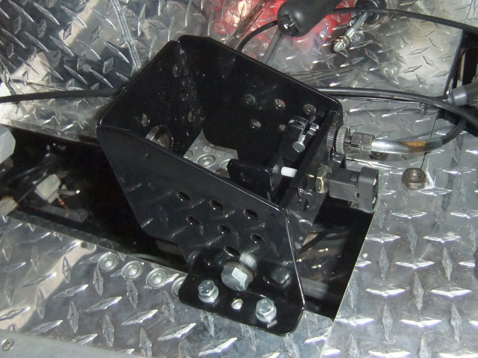
Racked, but this time it's steering. The front louvred plate bearing my RAC and AA badges had to be removed to expose the steering rack brackets and Arthur had conveniently provided a small piece of packing material to be placed under the near side of the rack to level it up and that was fine. When I went to pass the bolts through the rear holes in the clamping bracket, they fouled the front engine bolt. This was because I had temporarily used the old bike bolts, which at the front, is too long by about four inches and the overhang got in the way. Fortunately I had recently placed an order with Westfield Fasteners which included the correct engine bolts. Once again the engine crane was deployed to take the weight of the engine whilst I changed the front bolt, the first photo shows the nut attached to the new front bolt just allowing clearance for the nut of the clamp bracket. No problem now, the rack was firmly bolted down and level.
I quickly realised it was easier to join the two sections of the column together at the middle UV joint, before passing it down through the cockpit and loosely bolting the sheath to the chassis brackets. It took a bit wriggling to get the bottom UV joint onto the racks splined shaft, but eventually it slid in and the bolt was passed through the groove in the splines. I tightened the four bolts at the brackets, adjusting the column so that it passed centrally between the clutch and brake pedal, but one of the bolts securing the mid UV joint kept knocking against both pedals as the shaft was turned.
I took it all out and cut off the protruding excess threaded part of both bolts with my disc cutter, cleaned up the ends and passed the column back in again, but it still fouls the break pedal, not ideal. I will try adjusting the brackets to see if a slight angle solves the problem, if not I will move the pedal box back an inch or so as I had placed it as far forward as it can go, allowing for my long legs.
That was yesterday and today I took it all out again as the front foot well bulkhead had to be riveted in place first, so that the steering column could be passed through the hole in the bulkhead. Once that was done, when I reinstalled the pedal box I moved it back a tad and the break pedal is now in front of the UV joint nut and there is no interference. There is, as the photo shows a large flat flange on the pedal, I imagine that this is to increase stiffness of the pedal and I see no reason why I couldn't grind a little away to allow clearance should I need all available leg room, but it might also be, that when the break system is pressurised with hydraulic fluid, the pedal won't depress anywhere near as far back as the UV joint, we shall see.
Final photo shows the bulkhead glued and riveted in place, despite putting the tube of adhesive sealant on top of the hall radiator overnight, it still took a mighty effort to squeeze it out of the tube. It obviously cooled off very quickly, maybe whilst in the garage I should keep it in a bucket of very hot water, that might be the answer on these cold mornings.
I quickly realised it was easier to join the two sections of the column together at the middle UV joint, before passing it down through the cockpit and loosely bolting the sheath to the chassis brackets. It took a bit wriggling to get the bottom UV joint onto the racks splined shaft, but eventually it slid in and the bolt was passed through the groove in the splines. I tightened the four bolts at the brackets, adjusting the column so that it passed centrally between the clutch and brake pedal, but one of the bolts securing the mid UV joint kept knocking against both pedals as the shaft was turned.
That was yesterday and today I took it all out again as the front foot well bulkhead had to be riveted in place first, so that the steering column could be passed through the hole in the bulkhead. Once that was done, when I reinstalled the pedal box I moved it back a tad and the break pedal is now in front of the UV joint nut and there is no interference. There is, as the photo shows a large flat flange on the pedal, I imagine that this is to increase stiffness of the pedal and I see no reason why I couldn't grind a little away to allow clearance should I need all available leg room, but it might also be, that when the break system is pressurised with hydraulic fluid, the pedal won't depress anywhere near as far back as the UV joint, we shall see.
Final photo shows the bulkhead glued and riveted in place, despite putting the tube of adhesive sealant on top of the hall radiator overnight, it still took a mighty effort to squeeze it out of the tube. It obviously cooled off very quickly, maybe whilst in the garage I should keep it in a bucket of very hot water, that might be the answer on these cold mornings.
Thursday, 30 January 2014
TREASURE
I am happy to report that things are back on track with Arthur and last Tuesday I and a chum had a trip down to Ditchling in Sussex to visit Arthur in his man cave, well actually much more like a cavern. I can only dream of having so much space and that many tools, even if I knew what to do with them. Two left hand drive Beetle Backs were in production for customers in the USA, but most importantly there was a pile of goodies that had my name on them. TREASURE, steering rack, steering column, petrol tank, pedal box, master cylinders, handbrake lever and brake lines, now we can really get a move on.
Suspension shouldn't be much longer and an order was confirmed for exhaust pipes, dashboard, gear linkage, prop shafts, reversing gearbox etc. I had a list of queries which we talked through and I came away very excited and anxious to get the spanners out.
Despite the cold damp weather I wrapped up well and laid my new goodies out for the obligatory photo, the petrol tank although in its correct position has yet to be bolted down, but came complete with a lovely Monza style filler cap.
First job was to fit the pedals into the pedal box, the fit of each pedal on the shaft was too snug and the surplus black powder coat paint had to be filed away. It was the same problem between each pedal, but with some serious filing the pedals eventually swung freely back and forth after the box was bolted down. I intended to fit the bikes original clutch cable, but I had to drill out the hole at the top of the pedal for the nipple and also to widen the split to allow the nipple to rotate freely. I used the old hand break adjuster and although the cable is a tad too long I found a good route for it, that is out of sight with no tight bends and it works well. The photo show the mechanical break warning light fitted, but the rod from the master cylinder needs to be shortened and a clevis fitted before that can be bolted on.
Next job is to fit the steering rack and column, better get the steering wheel ordered.
Wednesday, 22 January 2014
RACKED
The little job of the luggage rack that I mentioned in the my last posting is now almost complete. The wood supports have to be removed and given a final sanding before varnishing. The aluminium straps are 30mm wide by 2mm deep, there is very slight flexing, but I thought that if I went up to 3mm I might have trouble bending the little upstand at the tail end, that I considered necessary to prevent luggage from slipping backwards under fierce acceleration. May be a quaint wicker basket would be appropriate? I think it looks the business and that the proportions are right. By the way, the little pot of paint was exactly the right size to give me the line to grind and sand the ends to.
The 6mm countersunk bolts go all the way through the wood and the GRP before being bolted up behind two 20mm wide ali strips, one fore and the other aft, that run from side to side so the stress on the GRP is spread evenly. When the rack is finally attached, probably after the car is sprayed, I will use a length of double sided tape between the the wood and the GRP to take up any gaping between the two
On a sadder note my relationship with Arthur of Aerocyclecar, the maker and supplier of my kit has come to an end. This will make the project a little more challenging as I will now have to independently source parts, but I have been promised help in that direction from somebody, who completed his car last year. With a bit of luck it may be quicker this way, although some parts may have to be special one offs, but one step at a time and the first is steering and suspension, I''ll let you know.
Saturday, 11 January 2014
CHRISTMAS BLING
Happy New Year to anyone reading this post and to celebrate it I have attached three of my wife's Christmas presents to the car.
First on was the Spread Eagle bonnet mascot, not quite the same, but very similar to Moto Guzzi's eagle motif that I applied to the alternator cover.Then the replica RAC and AA badges were pop riveted on, just to add a bit of nostalgia, those were the days, when a patrolman would snap a smart salute to a passing car bearing the appropriate badge
Next job is to make the luggage rack for the back of the car. I have a length of African hard wood, which my circular saw will cut down the middle to create the supports for the ali strips. The hard bit will be getting the underside of the wood to the same curvature of the GRP back panel, but I am sure I'll get there in the end.
Subscribe to:
Posts (Atom)